Aerodynamics
Table of Contents
-
Aerodynamic Theory
Introduction to Aerodynamic Theory
Aerodynamic theory lies at the heart of aviation, encompassing a comprehensive understanding of the forces, principles, and factors that govern flight. It is a multifaceted field that covers concepts such as aerodynamic forces, aircraft thrust, principles of lift, aerodynamic factors, and high-speed aerodynamics. These elements collectively shape the design, performance, and operation of aircraft, influencing everything from stability and efficiency to speed and maneuverability. By delving into the intricacies of aerodynamics, aviation professionals unlock the secrets of flight, enabling them to push the boundaries of innovation and enhance the safety and efficiency of air travel.
Aerodynamic forces play a pivotal role in flight dynamics, with lift, drag, thrust, and weight acting in concert to determine an aircraft's behavior in the air. Understanding how these forces interact is essential for achieving stability, maneuverability, and efficiency during flight operations. Meanwhile, aircraft thrust serves as the driving force behind propulsion, propelling aircraft forward through the air and overcoming drag. Optimizing thrust performance involves a deep understanding of propulsion systems, engine design, and the factors that influence thrust production, such as air density, velocity, and temperature.
In the realm of high-speed aerodynamics, aircraft encounter unique challenges related to airflow, shockwaves, and aerodynamic heating. High-speed flight requires specialized design considerations to mitigate these challenges and ensure the safety and stability of the aircraft. By exploring the intricacies of high-speed aerodynamics, engineers can develop innovative solutions to push the limits of aircraft speed and performance, paving the way for advancements in supersonic and hypersonic flight. Overall, a comprehensive understanding of aerodynamic theory is essential for advancing aviation technology and shaping the future of air travel.
The evolution of aircraft design over the years stands as a testament to the profound impact of aerodynamic theory on aviation innovation. Armed with a deep understanding of aerodynamic principles, engineers have continuously pushed the boundaries of what is possible in aircraft design, leading to remarkable advancements in performance, efficiency, and safety. From the pioneering efforts of the Wright brothers to the cutting-edge technologies of modern aerospace companies, each generation of aircraft reflects the culmination of decades of aerodynamic research and experimentation. Innovations such as swept wings, laminar flow control, and composite materials have revolutionized the industry, enabling aircraft to fly faster, farther, and with greater fuel efficiency than ever before. Furthermore, advancements in computational fluid dynamics (CFD) and wind tunnel testing have provided engineers with powerful tools to analyze and optimize aircraft designs, leading to unprecedented levels of aerodynamic performance. As we continue to expand our knowledge of aerodynamics, we can expect even more groundbreaking innovations that will shape the future of flight and redefine the possibilities of air travel.
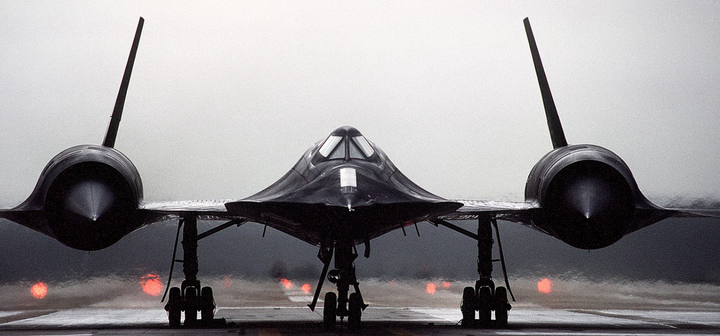
Figure 1 - A front view of an SR-71 aircraft assigned to Detachment 4, 9th Strategic Reconnaissance Wing, as it prepares for takeoff
Aerodynamic Forces
In the realm of aerodynamics, four fundamental forces intricately govern the flight of an aircraft: lift, drag, thrust, and weight.
Lift - often considered the most essential force for flight, acts perpendicular to the relative airflow and enables an aircraft to ascend and remain airborne. This force is generated primarily by the wings through their unique shape, known as an airfoil, and is influenced by factors such as airspeed, angle of attack, and wing geometry. Engineers meticulously design wings to maximize lift production while minimizing drag, resulting in efficient and stable flight characteristics.


Thrust
Lift
Weight
Drag
Forces of Flight
Drag - the aerodynamic force acting parallel to the relative airflow, opposes the forward motion of the aircraft and is a significant factor in determining fuel consumption and speed capabilities. It arises due to the friction between the aircraft and the air molecules, as well as the pressure differential created by the shape of the aircraft. Various forms of drag, including parasite drag from the aircraft's body and induced drag from lift production, must be carefully managed through aerodynamic design and optimization to enhance flight efficiency and performance.
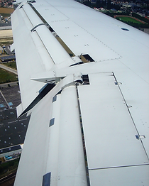

Figures 4-5 - Flaps deployed from the trailing edge of the wings increase drag, enabling aircraft of all sizes to slow down and execute steeper-than-normal approaches during landing.
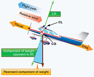
Figures 2-3 - the four aerodynamic forces of flight (top) and force vectors on an aircraft during a stabilized climb (bottom)
Thrust - the propulsive force that enables an aircraft to overcome drag and propel forward through the air. Generated by engines or propulsion systems, thrust acts in opposition to drag and facilitates sustained flight and controlled motion. Engine design, propulsion technologies, and operating parameters such as throttle settings and air density all influence thrust production. Optimizing thrust performance is crucial for achieving desired flight characteristics, including speed, range, and maneuverability, and is a key focus area for aircraft engineers and manufacturers.
Weight - the fourth and final aerodynamic force, acts downward toward the center of the Earth and is countered by lift during flight. It encompasses the total mass of the aircraft, including the structure, payload, fuel, and passengers. Maintaining a balance between lift and weight is essential for achieving level flight and controlling altitude changes. Understanding the interplay between these four forces is essential for designing aircraft with optimal performance, stability, and efficiency, paving the way for advancements in aviation technology and shaping the future of air travel.
Angle of Attack
The aircraft angle of attack refers to the angle between the chord line of the wing (an imaginary straight line connecting the leading and trailing edges of the wing) and the relative airflow approaching the wing. It is a crucial parameter in aerodynamics as it directly influences the lift and drag forces acting on the aircraft. As the angle of attack increases, the lift force initially increases until reaching a critical point, after which it begins to decrease. Simultaneously, the drag force increases with the angle of attack, reaching a maximum at a certain angle. Pilots carefully monitor and control the angle of attack during various phases of flight to optimize aircraft performance and safety. The critical angle of attack refers to the maximum angle of attack at which the wing can produce lift efficiently before experiencing an aerodynamic stall. Beyond this critical angle, the smooth flow of air over the wing separates, causing a sudden loss of lift and a significant increase in drag. An aerodynamic stall occurs when the angle of attack exceeds that critical angle, leading to a disruption in the airflow over the wing surfaces. During a stall, the wing loses its ability to generate lift effectively, resulting in a loss of altitude and potential loss of control if not managed promptly. The critical angle of attack varies from one aircraft to another and depends on factors such as wing design, airspeed, and aircraft configuration. As a pilot, you will undergo extensive training to recognize the signs of an impending stall in various power-on and power-off conditions starting at the private pilot level and employ proper recovery techniques to safely regain control of the aircraft.
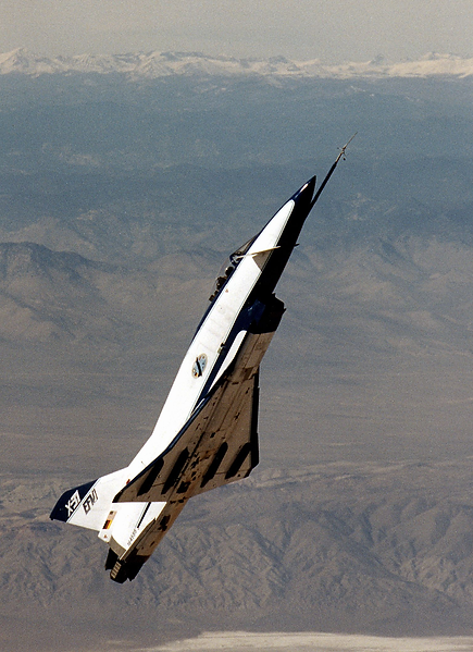
Figure 8 - NASA X-31 Demonstrating High Angle of Attack
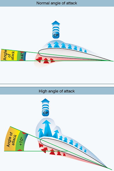
Figure 6 - normal and high angles of attack on an airfoil
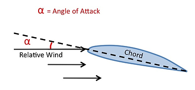
Figure 7 - angle of attack diagram
An aircraft can stall at any speed and configuration because the stall is primarily determined by the critical angle of attack, not the airspeed or configuration. Aircraft can stall at any airspeed and configuration but only one critical angle of attack. The critical angle of attack is a function of the wing's aerodynamic characteristics, such as its shape and design, rather than the aircraft's speed or configuration. Regardless of the aircraft's speed or configuration, if the angle of attack exceeds the critical AOA, the wing will stall. In contrast, airspeed and configuration affect the lift and drag forces acting on the aircraft, but they do not directly determine the onset of a stall. Different airspeeds and configurations may result in varying amounts of lift and drag, influencing the aircraft's performance and handling characteristics, but they do not alter the critical angle of attack required for the full stall onset. This distinction underscores the importance of recognizing and understanding the critical angle of attack during flight operations.
Aircraft Thrust
Thrust plays a pivotal role in the dynamics of flight, serving as the propulsive force that enables aircraft to move forward through the air. Rooted in the principles of aerodynamic theory, thrust is generated by the propulsion system of an aircraft, typically powered by propeller, turbofan, turboprop, or jet engines. The production of thrust involves the acceleration of air mass in the engine's intake, combustion of fuel to increase energy content, and expulsion of high-velocity exhaust gases from the engine nozzle. In small aircraft, thrust plays a crucial role in propelling the aircraft forward through the air. Unlike larger commercial airliners that often utilize turbofan or turbojet engines, small aircraft commonly employ piston engines or turboprop engines to generate thrust. In piston-engine aircraft, thrust is generated through the combustion of aviation fuel within the engine cylinders, which drives pistons to produce rotational motion. This rotational motion is transmitted to the propeller, which converts it into thrust by accelerating a mass of air rearward. Similarly, turboprop engines harness the energy of combustion to drive a turbine, which powers a propeller to produce thrust. On an aerodynamic level, thrust is the force exerted by the propulsion system of the aircraft in the forward direction, according to Newton's third law of motion. Newton's third law of motion states that for every action, there is an equal and opposite reaction. In the context of aircraft propulsion, the action of expelling exhaust gases rearward produces an equal and opposite reaction in the forward direction, resulting in thrust. A key aspect of thrust production is understanding the factors that influence its magnitude and effectiveness. Air density, temperature, and pressure, along with engine design parameters such as airflow velocity and fuel-to-air ratio (mixture), all impact the thrust output of an aircraft's propulsion system. At higher altitudes, where air density is lower, engines may produce less thrust due to reduced air mass available for combustion. Additionally, variations in airspeed, such as during takeoff, climb, cruise, and descent, necessitate adjustments in engine power settings to maintain desired thrust levels while optimizing fuel efficiency.

Figure 9 - Bombardier CRJ-900, a regional jet aircraft, is typically powered by two General Electric CF34-8C5 turbofan engines. Each CF34-8C5 engine is capable of producing a maximum thrust output of approximately 14,510 pounds-force (64.6 kN) under standard operating conditions. Therefore, when both engines are operating at maximum thrust, the CRJ-900 can generate a combined thrust of around 29,020 pounds-force (129.2 kN).
The aerodynamic theory behind thrust generation delves into the intricacies of fluid dynamics, combustion processes, and propulsion system design. Turbofan engines, commonly used in commercial airliners like the Boeing 737 or Bombardier CRJ-900 [Figure 9], incorporate a fan at the front of the engine that compresses incoming air, augmenting the volume of air available for combustion. This process, known as bypass airflow, contributes to increased thrust efficiency by accelerating a larger mass of air at a relatively lower velocity. In contrast, turbojet engines, such as those found in military fighter jets like the F-16 or F-22, rely primarily on the combustion of fuel within the engine core to produce high-velocity exhaust gases, resulting in greater thrust but lower fuel efficiency compared to turbofans. Engineers continuously strive to enhance the performance and efficiency of aircraft propulsion systems through advancements in aerodynamic design, materials technology, and propulsion system integration. By refining engine components, optimizing airflow management, and integrating innovative technologies such as variable geometry engine nozzles or high-bypass turbofan architectures, they can achieve higher thrust-to-weight ratios, improved fuel efficiency, and reduced environmental impact.
Principles of Lift
For student pilots embarking on their journey into the world of aviation, understanding the principles of lift is paramount. Lift is the aerodynamic force that enables aircraft to overcome gravity and ascend into the skies. It is a fundamental concept that forms the backbone of flight mechanics, influencing every aspect of aircraft design, operation, and performance. By comprehending these principles, student pilots gain a solid foundation upon which to build their knowledge and skills, paving the way for safe and successful journeys through the skies. Lift is generated by the interaction between an aircraft's wings and the surrounding air. The shape of the wing, known as an airfoil, plays a central role in lift generation. As air flows over the curved surface of the airfoil, it is subjected to different pressures, with lower pressure on the upper surface and higher pressure on the lower surface. This pressure differential creates a lifting force perpendicular to the direction of airflow, known as lift. The magnitude of lift is determined by various factors, including the airfoil's shape, angle of attack, airspeed, and air density.

Figure 10 - airflow over an airfoil producing lift
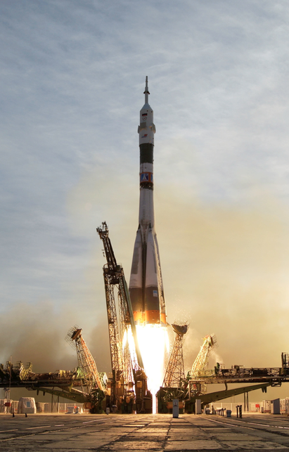
Figure 11 - NASA Soyuz TMA-5 spacecraft lifts off from the Baikonur Cosmodrome in Kazakhstan October 14, 2004
Bernoulli's principle is a fundamental concept in fluid dynamics that states that an increase in the speed of a fluid occurs simultaneously with a decrease in pressure. Applied to aviation, this principle explains the generation of lift on airfoils, the wing-shaped structures of aircraft. As air flows over the curved upper surface of an airfoil, it must travel a greater distance and thus accelerates, according to Bernoulli's principle. Consequently, the air pressure above the wing decreases, creating a region of lower pressure compared to the air pressure below the wing.
This pressure differential results in a net upward force, known as lift, acting perpendicular to the direction of the airflow. The higher pressure beneath the wing contributes to this force, effectively lifting the aircraft against the force of gravity. For aircraft, Bernoulli's principle has profound implications for design and performance. Airfoils are carefully crafted to exploit this principle, with curved upper surfaces and flatter lower surfaces that facilitate the creation of lift. By adjusting the angle of attack—the angle at which the wing meets the oncoming airflow—pilots can manipulate the lift generated by the wing. Increasing the angle of attack increases the pressure differential and, consequently, the lift force. However, there is a critical angle of attack beyond which the airflow over the wing becomes turbulent, leading to a sudden decrease in lift and a potential aerodynamic stall.
Aerodynamic Factors in Flight
Aircraft experience a multitude of aerodynamic factors during flight, each of which significantly influences its performance and handling characteristics. These factors vary depending on the aircraft's configuration, maneuvers, load factors, and environmental conditions. Understanding how aerodynamics change in different scenarios is essential for pilots to maintain safe and controlled flight operations. During various configurations such as level flight, climbs, descents, and turns, aerodynamic forces act differently on the aircraft. For instance, in a turn, the aircraft's wings generate both lift and centrifugal force. The lift component counters the aircraft's weight, while the centrifugal force acts outward from the center of the turn, causing the aircraft to bank. Pilots must coordinate their control inputs to maintain balance and prevent overbanking, which can lead to loss of control. Attitudes in aviation refer to the orientation of an aircraft relative to the horizon and its flight path. Common attitudes include level flight, climbs, descents, turns, and various performance and aerobatic maneuvers. Stability, both longitudinal and lateral-directional, plays a critical role in maintaining desired attitudes and controlling the aircraft's motion. Longitudinal stability ensures that the aircraft returns to its trimmed angle of attack following disturbances, such as gusts or control inputs, while lateral-directional stability prevents unwanted deviations from the desired flight path, such as Dutch roll or spiral instability.

Figure 11 - [A] Pitch attitude is the angle formed between the airplane’s longitudinal axis, which extends from the nose to tail of the airplane, and the natural horizon. [B] Bank attitude is the angle formed by the airplane's lateral axis, which extends from wingtip to wingtip, and the natural horizon.
Slips and skids represent two distinct aerodynamic phenomena that occur when an aircraft's flight path deviates from its longitudinal axis. In a slip, the aircraft's nose is yawed in the opposite direction of the bank angle. Pilots may intentionally employ slips during approaches or landings to increase drag and control descent rates without gaining excessive airspeed. Conversely, a skid occurs when the aircraft's nose yaws toward the direction of the bank, indicating uncoordinated flight. Skids can result from excessive rudder input or inadequate coordination of control inputs during turns. Maintaining coordinated flight is essential for optimizing lift production, minimizing drag, and ensuring stable and efficient flight operations.
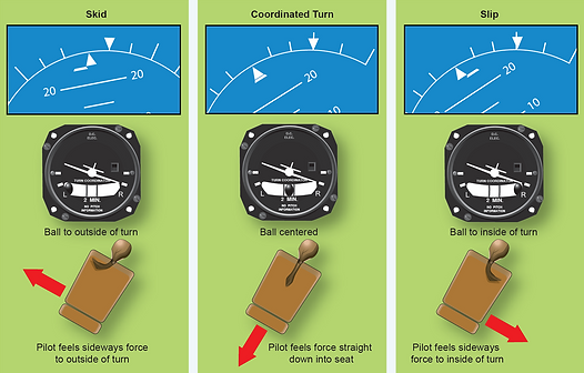
Figure 12 - Indications of a slip and skid
Aircraft load factors, expressed in "G's," are a measure of the forces experienced by an aircraft during flight relative to the force of gravity. In straight and level flight, the load factor is typically 1G, indicating that the total lift produced by the wings equals the aircraft's weight. However, during maneuvers such as turns, climbs, or descents, the load factor increases, subjecting the aircraft and its occupants to additional forces. For example, in a 30-degree bank turn, the load factor increases to approximately 1.15G. This means that the total lift generated by the wings is 15% greater than the aircraft's weight, resulting in an increased sensation of gravity for the occupants. As the bank angle increases, so does the load factor experienced by the aircraft. In a 45-degree bank turn, the load factor reaches approximately 1.41G. This means that the total lift produced by the wings is 41% greater than the aircraft's weight, resulting in a noticeable increase in the sensation of gravity.
Coordinated and uncoordinated turns refer to the manner in which an aircraft's control surfaces are manipulated to execute a turn. In a coordinated turn, the aircraft's control inputs are harmonized to maintain balanced flight, with the aircraft's bank angle and rate of turn aligned with the direction of the nose. This is indicated in the turn coordinator by the black ball being centered or lower white bar centered on the heading triangle. [Figure 12] Proper coordination involves synchronized use of the ailerons, rudder, and elevator to achieve smooth and controlled turns. In contrast, an uncoordinated turn occurs when there is a disparity between the aircraft's bank angle and the direction of the nose, often resulting from excessive or insufficient rudder input. This is indicated in the turn coordinator by the ball outside or inside of the turn, indicated which side's rudder input is required in order to return to coordinated flight. Uncoordinated turns can lead to adverse yaw, increased drag, and decreased lift production, compromising the aircraft's stability and maneuverability.
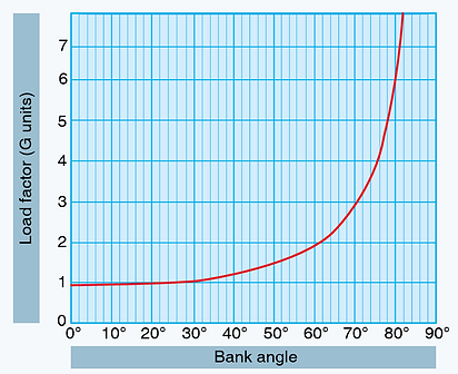
Figure 13 - Aircraft bank angle and load factor (G units)
In a 60-degree bank turn, the load factor climbs to approximately 2G. This means that the total lift generated by the wings is double the aircraft's weight, resulting in a significant increase in the forces experienced by both the aircraft and its occupants. Pilots must exercise caution when performing steeply banked turns to prevent overstressing the aircraft's structure and to maintain control throughout the maneuver.
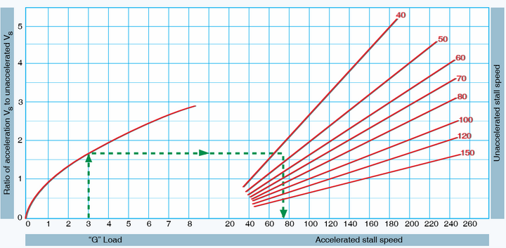
Figure 14 - Load factor changes aircraft stall speed
The increase in g load, or load factor, directly impacts an aircraft's stall speeds, both accelerated and unaccelerated. As the load factor increases, the wing's effective angle of attack also increases, leading to a higher stall speed. Accelerated stalls occur when an aircraft is subjected to increased g loads, such as during steep turns or abrupt maneuvers, causing the wing to stall at a higher airspeed than in straight and level flight. The higher load factor increases the wing's critical angle of attack, necessitating a higher airspeed to maintain lift. Conversely, unaccelerated stalls occur in straight and level flight or gentle maneuvers and are characterized by the aircraft reaching its stall speed at the published value for the specific configuration and weight. Pilots must be mindful of the impact of load factor on stall speeds and adjust their flying techniques accordingly to maintain safe and controlled flight operations.
In the event of an aerodynamic stall, where the critical angle of attack is exceeded, the airflow over the wings becomes separated, leading to a loss of lift and control. Stalls can occur during slow flight, high-load maneuvers, or improperly executed maneuvers. Proper stall recovery techniques, such as reducing the angle of attack, applying power, and maintaining coordinated flight, are essential for pilots to regain control and prevent a dangerous situation. Aerodynamic factors can also lead to unusual attitudes, upsets, and spins, where the aircraft enters an unexpected and potentially hazardous flight condition. Unusual attitudes may result from turbulence, wake encounters, or pilot disorientation. Spins, characterized by a sustained autorotation around the vertical axis, occur when the aircraft enters a stalled condition with one wing more deeply stalled than the other. Effective spin recovery techniques involve reducing the angle of attack, applying opposite rudder to counter yaw, and smoothly recovering from the dive.
Airframe Design
Airframe design is a fundamental aspect of aerospace engineering, encompassing the structural framework and configuration of an aircraft. It involves the intricate balance between aerodynamics, materials science, and structural engineering to create aircraft with optimal performance, safety, and efficiency. From the graceful curves of a wing to the robust fuselage construction, every element of an aircraft's airframe is meticulously designed to withstand the forces encountered during flight while minimizing weight and maximizing aerodynamic performance. In this subject, we delve into the principles, components, and methodologies behind the aircraft and airframe design, exploring the intricacies of shaping aircraft to navigate the skies with precision and reliability.
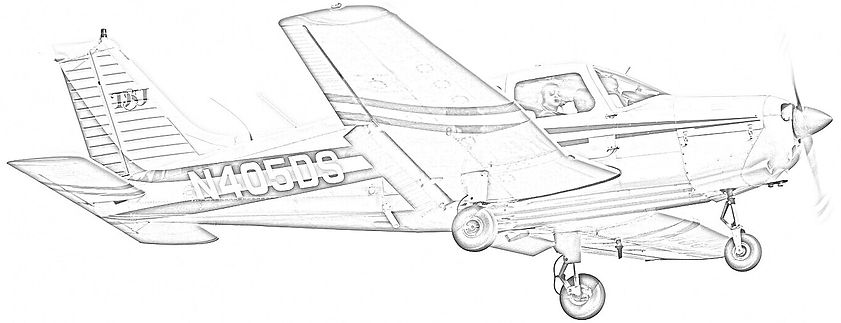
Figure 15 - The Piper PA-28-151 features a sleek and aerodynamically efficient airframe design, optimized for stability and performance during training flight
Parts of an Aircraft
-
Fuselage: The fuselage is the central body of an aircraft, housing the cockpit, cabin, cargo compartments, and crucial flight systems. In airframe design, the fuselage serves as the primary structural component that connects the various other elements of the aircraft, such as the wings and empennage. Its shape and construction are critical for maintaining aerodynamic efficiency and structural integrity. Aircraft manufacturers carefully design the fuselage to minimize drag while accommodating necessary internal components and payloads. Additionally, the fuselage design influences the aircraft's stability and handling characteristics, particularly during maneuvers such as pitch and yaw.
-
Wings: Wings are the primary lifting surfaces of an aircraft, responsible for generating the aerodynamic forces needed to support its weight and achieve flight. [Figure 16] In airframe design, wings are meticulously shaped to optimize lift-to-drag ratios, ensuring efficient and stable flight across a range of operating conditions. Engineers consider various factors such as wing aspect ratio, airfoil profile, wing sweep, and wingtip design to maximize aerodynamic performance while minimizing induced drag and stall tendencies. Furthermore, wings often incorporate additional features such as flaps, slats, and spoilers to enhance lift and control during takeoff, landing, and maneuvering.

Figure 16 - Components of an aircraft wing
-
Empennage: The empennage, also known as the tail assembly, comprises the horizontal stabilizer, vertical stabilizer, and associated control surfaces such as elevators and rudders. [Figure 17] In airframe design, the empennage plays a crucial role in stabilizing and controlling the aircraft's pitch, yaw, and roll motions. By adjusting the angles of the horizontal and vertical stabilizers, pilots can trim the aircraft to maintain level flight and counteract external forces such as wind gusts or control inputs. Additionally, the empennage houses critical flight control mechanisms, allowing pilots to precisely command the aircraft's attitude and direction.
-
Horizontal Stabilizer: The horizontal stabilizer is a fixed or adjustable surface located at the rear of the aircraft's empennage, parallel to the wings. In airframe design, the horizontal stabilizer serves to maintain longitudinal stability by counteracting pitch changes induced by various flight conditions. By adjusting the angle of incidence or incorporating aerodynamic features such as elevators or trim tabs, pilots can trim the aircraft to maintain desired pitch attitudes during different phases of flight.
-
Elevator: The elevator is a movable control surface attached to the trailing edge of the horizontal stabilizer, typically hinged to allow for up and down movement. In airframe design, the elevator is responsible for controlling the aircraft's pitch attitude by deflecting airflow over the horizontal stabilizer. By adjusting the elevator position, pilots can generate nose-up or nose-down pitching moments, facilitating changes in altitude and airspeed.
-
Vertical Stabilizer: The vertical stabilizer is a fixed or adjustable surface located vertically at the rear of the aircraft's empennage, perpendicular to the wings. In airframe design, the vertical stabilizer serves to provide directional stability and control by counteracting yawing moments induced by factors such as crosswinds or asymmetric thrust. Aerospace engineers design the vertical stabilizer to resist adverse yaw effects and maintain aircraft alignment with the intended flight path. By incorporating a rudder or trim tabs, pilots can adjust the aircraft's yaw attitude to coordinate turns and maintain directional control during flight.
-
Rudder: The rudder is a movable control surface attached to the trailing edge of the vertical stabilizer, typically hinged to allow for left and right movement. In airframe design, the rudder is responsible for controlling the aircraft's yaw attitude by deflecting airflow over the vertical stabilizer. By adjusting the rudder position, pilots can generate yawing moments, facilitating coordinated turns and maintaining directional control in adverse conditions. Damage done to the aircraft rudder or horizontal stabilizer in flight can prove catastrophic for flight crews and passengers alike. [Figure 18]
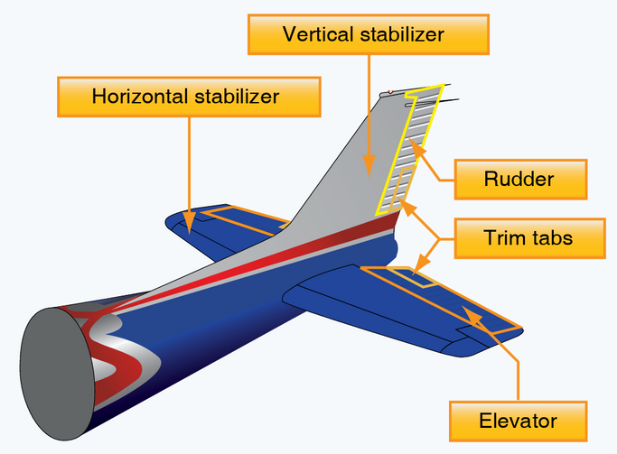
Figure 17 - Components of an aircraft empennage

Figure 18 - Damage done to a Concorde rudder after an incident in 1989
-
Landing Gear: Landing gear encompasses the wheels, struts, and associated mechanisms that support an aircraft during takeoff, landing, and ground operations. [Figures 20-21] In airframe design, landing gear is carefully engineered to provide structural strength, shock absorption, and stability while minimizing weight and drag. Depending on the aircraft's design and intended use, landing gear configurations can vary from simple fixed gear setups to more complex retractable or tricycle arrangements. Additionally, modern landing gear designs often incorporate features such as anti-skid brakes, shock absorbers, and steering mechanisms to enhance safety and maneuverability on the ground.
-
Flaps: [Figure 19] Flaps are hinged aerodynamic surfaces mounted on the trailing edge of an aircraft's wings, primarily used to increase lift and drag during various stages of flight. Flaps are commonly used during all landing procedures to allow the aircraft to make a steeper than normal descent but they can also be used during performance takeoffs to increase lift and shorten the takeoff roll. In airframe design, flaps are carefully engineered to modify the wing's camber and increase its surface area, thereby enhancing lift production while minimizing drag.
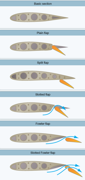
Figure 19 - Types of flaps
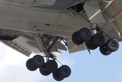
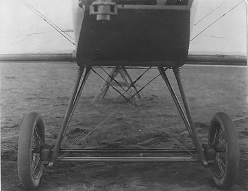
Figure 20 - The landing gear of an American Airlines Boeing 777-200ER, a few seconds before landing at London Heathrow Airport
Figure 21 - Landing Gear on an aircraft in 1914 from the US National Archives
Aircraft Stability
Aircraft Stability refers to the ability of an aircraft to maintain a specific flight attitude without the need for constant control input from the pilot. [Figure 22] It is a critical aspect of aircraft design that directly impacts safety, performance, and flight characteristics. The two primary types of stability are static stability, which pertains to the immediate response of the aircraft to disturbances, and dynamic stability, which is concerned with the aircraft’s response over time. In the context of aircraft, stability is often categorized into three axes: longitudinal (pitch), lateral (roll), and vertical (yaw). Each axis has its own stability considerations and is influenced by various factors such as the aircraft’s center of gravity, wing placement, tail design, and control surfaces.
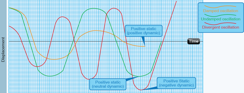
Figure 22- damped vs. undamped stability
Static Stability
Positive static stability occurs when the aircraft returns to its original equilibrium position [Figure 23] after being disturbed, such as by a gust of wind or a pilot input. For example, if the aircraft pitches nose-up due to a gust of wind, a positively statically stable aircraft will tend to return to its original trimmed angle of attack. This stability characteristic is desirable as it ensures that the aircraft naturally seeks its stable equilibrium, providing pilots with a stable platform for control inputs and reducing the need for constant manual intervention to maintain desired flight attitudes.
Neutral static stability describes an aircraft configuration where there is no tendency for the aircraft to return to its original trimmed state after being disturbed. Instead, the aircraft maintains its new equilibrium position without further deviation. For instance, if a neutrally statically stable aircraft experiences a pitch disturbance, it will maintain its new angle of attack indefinitely unless a corrective control input is applied by the pilot. Neutral static stability is typically observed in aircraft designed for high maneuverability, such as fighter jets, where maintaining a constant deviation from trimmed flight is desirable for agile maneuvering capabilities.
Negative static stability occurs when an aircraft diverges further from its original trimmed state following a disturbance. In this scenario, the aircraft amplifies the initial displacement rather than returning to its equilibrium position. For example, if a negatively statically stable aircraft experiences a pitch disturbance, it will continue to pitch nose-up or nose-down, leading to uncontrollable oscillations or departure from controlled flight if left unchecked. Negative static stability is highly undesirable in aircraft design, as it can result in dangerous flight conditions and loss of control. Engineers strive to design aircraft with positive or neutral static stability characteristics to ensure safe and stable flight operations across a wide range of conditions.
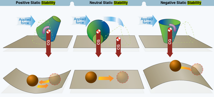
Figure 23 - various types of static stability
Dynamic Stability
Positive dynamic stability occurs when the aircraft naturally damps out oscillations and returns to its original flight path following a disturbance. This is analogous to a pendulum returning to its resting position after being displaced. In aviation, positive dynamic stability ensures that the aircraft remains stable and controllable, reducing the pilot's workload and enhancing safety. For example, if an aircraft experiences turbulence that causes it to roll or pitch, positive dynamic stability will cause the aircraft to gradually return to level flight without requiring continuous corrective inputs from the pilot.
Neutral dynamic stability describes a condition where the aircraft maintains a constant deviation from its original flight path after being disturbed. In this state, the aircraft neither dampens nor amplifies oscillations over time but instead maintains a steady deviation. Neutral dynamic stability can be advantageous in certain flight regimes where maneuverability or agility is prioritized over stability, such as in aerobatic or fighter aircraft. However, it requires constant pilot attention to maintain desired flight attitudes and can lead to increased workload during flight operations.
Negative dynamic stability occurs when the aircraft's response to a disturbance amplifies over time, leading to divergent behavior and loss of control. This is akin to a ball perched on top of an upside-down bowl—it will continue to roll away from its equilibrium position unless acted upon by an external force. In aviation, negative dynamic stability is highly undesirable as it can lead to unstable flight conditions and pose a significant safety risk. Engineers meticulously design aircraft to exhibit positive or neutral dynamic stability characteristics, ensuring that they remain stable and controllable throughout a wide range of operating conditions.
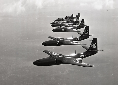
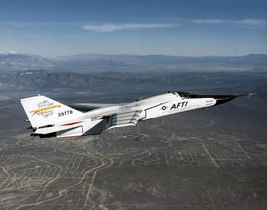
Figures 24-25 - the ability to maintain precise aircraft stability is especially important when conducting formation or supersonic flight
Longitudinal, Lateral, and Directional Stability
Aircraft longitudinal stability primarily concerns the aircraft's stability along its longitudinal axis, which runs from the nose to the tail. [Figure 26] It involves controlling the aircraft's pitch motion, where pitch refers to the up and down movement of the nose of the aircraft. Longitudinal stability ensures that the aircraft naturally returns to its trimmed angle of attack after being perturbed, such as by a gust of wind or a pilot input. In other words, if the aircraft pitches nose-up or nose-down due to an external force, longitudinal stability will cause it to return to its original trimmed pitch attitude without requiring continuous pilot intervention. This stability is crucial for maintaining a steady and predictable flight path, as well as for providing a comfortable and safe experience for passengers.
Lateral stability focuses on the aircraft's stability along its lateral axis, which runs from wingtip to wingtip. It primarily involves controlling the aircraft's roll motion, where roll refers to the tilting of the aircraft from side to side. Lateral stability ensures that the aircraft resists excessive rolling motions and maintains a wings-level attitude during flight. If the aircraft experiences a roll disturbance, lateral stability will cause it to return to wings-level flight by generating a rolling moment in the opposite direction of the disturbance. This stability characteristic is essential for maintaining coordinated flight and preventing uncontrolled bank angles, especially during turns and maneuvers.
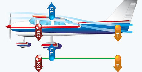
Figure 26 - Longitudinal stability
Directional stability pertains to the aircraft's stability along its vertical axis, which runs from the top to the bottom of the aircraft. It primarily involves controlling the aircraft's yaw motion, where yaw refers to the rotation of the aircraft around its vertical axis. Directional stability ensures that the aircraft maintains a straight flight path and resists deviations from the desired heading. If the aircraft experiences a yaw disturbance, directional stability will cause it to return to its original heading by generating a yawing moment in the opposite direction of the disturbance. This stability characteristic is critical for maintaining course accuracy, especially during crosswind conditions or when flying in turbulent air.
High-speed Aerodynamics

Figure 27 - A B-2 Spirit (Spirit of Missouri) at the Dyess AFB air show 2018
High-speed aerodynamics and supersonic flight pose unique challenges to aircraft designers and engineers due to the complex interactions of aerodynamic forces at high Mach numbers. At supersonic speeds, airflow over the aircraft's surfaces becomes highly compressed, leading to shock wave formation and significant changes in aerodynamic behavior. One critical phenomenon in supersonic flight is the formation of shock waves, which are abrupt changes in air pressure and density that occur when the aircraft exceeds the speed of sound. These shock waves propagate away from the aircraft's surfaces and can have profound effects on its aerodynamic performance, including increased drag, decreased lift, and changes in stability and control characteristics. Engineers use computational fluid dynamics (CFD) simulations and wind tunnel testing to study shock wave interactions and optimize aircraft designs for efficient supersonic flight.
Another key aspect of high-speed aerodynamics is the concept of wave drag, which arises due to the formation of shock waves and the resulting increase in drag as the aircraft approaches and exceeds the speed of sound. Wave drag becomes increasingly significant as the aircraft accelerates through the transonic region, where airflow transitions from subsonic to supersonic speeds. Engineers employ various aerodynamic techniques, such as minimizing cross-sectional area and streamlining the aircraft's contours, to reduce wave drag and improve overall aerodynamic efficiency. Additionally, advanced design features such as swept wings, supersonic inlet designs, and adjustable control surfaces are utilized to mitigate the adverse effects of wave drag and enhance the aircraft's performance in supersonic flight regimes. Furthermore, supersonic flight introduces additional aerodynamic challenges related to stability and control. At high speeds, the aerodynamic forces acting on the aircraft can lead to changes in its stability characteristics, including pitch, roll, and yaw stability. Control systems must be optimized to provide precise and responsive handling at supersonic speeds, allowing pilots to maintain desired flight attitudes and maneuver safely.
